How Many Sprinkler Heads Per Pipe Size
THE GROUND RULES
Commencement a tip that just may save your behind!
 When in doubt, ever use a larger bore pipe!
It volition non harm anything to utilise a larger pipe size. Flow. If you are uncertain whether to use a 3/4″ or 1″ pipe, then you should apply the 1″. Using a larger size pipe is ALWAYS the safest selection.
No, I don't own stock in an irrigation pipage manufacturer and I'm not getting kickbacks for pushing bigger pipe! Unlike habiliment, piping tin never be "likewise large". Reverse to what might appear to be truthful, forcing water into a smaller piping REDUCES the water pressure, and hurts sprinkler performance. This is because the smaller pipe creates more pressure loss due to friction and turbulence as the water flows through it. It'due south another of those hard to grasp hydraulic principles! Just remember that when it comes to pipe, bigger is meliorate! I'k always amazed at how many irrigation equipment sales people don't know this most basic of irrigation rules. I've had clients tell me they were told to utilize a smaller piping to proceed the pressure upwards past tech support people at some of the major sprinkler manufacturer's. That'southward an manufacture disgrace!
And so one more fourth dimension to drill it into your head– You don't subtract the pipe size to keep the pressure up- or down for that affair. That is totally, completely, wrong. The reason we use smaller pipage is to save money. Which of grade, is a good reason! For those who want more specifics on this, there is a very boring scientific caption at the lesser of this page.
Is information technology Pipe or Tube? For the virtually part I use the term "pipage" rather than "tube" on this folio and elsewhere. Bad habit of mine (note that by reading advisedly, you have plant one of my faults!) The difference is the material they are made from. Steel and PVC plastic are more often than not chosen pipe. Polyethylene, PEX, and copper are usually referred to every bit tube. I often spiral up and call tube pipe! 🙂
TRIAL & ERROR METHOD TO DETERMINE LATERAL PIPE SIZE USING A SPREADSHEET
This method involves trying various piping sizes until a good combination is found.
Definitions you lot need to know:
Lateral pipage: all the pipes between the control valve and the sprinkler heads.
Mainline: The pipage that goes from the water source to the command valves.
Control Valve: The valve that turns on and off a grouping of sprinklers. Most often it is an electric valve operated by a timer.
Valve excursion: a single valve, and all the piping, fittings and sprinkler heads downstream from it. In other words, all the sprinkler heads that outset working when yous plough on the valve are part of the same valve excursion.
GPM: Gallons per minute, a measure of water menstruum charge per unit. Utilise primarily in the U.s..
PSI: Pounds per square inch, a measure of h2o pressure. Use primarily in the United States.
You lot volition need a spreadsheet Friction Loss Calculator.
Here'southward a folio with calculators for almost every type of pipe: Friction Loss Figurer Spreadsheets
Grab the appropriate spreadsheet for the type pipe you plan to use.
At present you lot just enter the appropriate data for each section of pipage into the figurer and and so read the total force per unit area loss at the bottom of the spreadsheet. If the pressure level loss is likewise loftier, then attempt making i of the lengths of pipe larger. The calculator volition also give you lot the water velocity in each section of pipe, and warn you if the velocity is besides high.
Detailed Instructions:
The best fashion to teach this is probably to walk you through a couple of examples.
![]()
If I may brand a suggestion, download the spreadsheet for Cl200 PVC now, and open it upwardly in a separate window. Then call up almost each footstep, enter the values I show into the spreadsheet, and actually try to indistinguishable what I do in the examples beneath. Something about really doing this helps engage people's brains. People tell me they read it twice and still don't get it when they just read it, only as soon as they actually Endeavor information technology, and then it suddenly makes sense. Information technology's called learning by doing, and it is considered the best teaching method. This process is unproblematic, All the same, it is not obvious and sounds illogical to those non trained in hydraulics.
A Uncomplicated Example:
 Example Plan
The sketch above is an instance of a very simple valve circuit with five sprinkler heads. In this instance the sprinklers are 15′ apart and each sprinkler uses 3.seven GPM of water. The reddish numbers on the sketch are the total water flow for each pipage section in GPM.
Let's assume nosotros want to use Cl200 PVC pipe and nosotros want a maximum total of 4 PSI of pressure loss in our lateral pipes.
If you are working through the Sprinkler Design Tutorial the maximum full force per unit area loss is entered on your Design Data Class in the Pressure Loss Table section. There you volition run into a figure you entered chosen "_____ PSI – Laterals". That is the maximum PSI loss for the laterals, utilize that number here. If in doubt, 3 PSI is a reasonably safe value for most sprinkler systems.
If you don't sympathize how to summate the water flow in each section (the cerise numbers) you should accept a wait at the Sprinkler Pipe Layout page.
Remember that the maximum total pressure loss between the valve and the final sprinkler may Non exceed 20% of the sprinkler head operating force per unit area.
Example: 20 PSI sprinkler operating pressure. 20 10 0.twenty = 4 PSI maximum pressure level loss in circuit laterals.
If you don't understand pressure level losses in irrigation, encounter Force per unit area Loss & Selecting Your Sprinkler Equipment.
For communication on types of piping (Cl200, poly, etc.) encounter Irrigation System Lateral Pipes.
To utilize the spreadsheet friction loss calculator to determine the pressure loss:
- Download and open the Friction Loss Reckoner.
- In that location is a line on the spreadsheet for each section of pipage. So for this example yous will enter data for 5 piping sections.
- Start with the pipe section closest to the valve as section #1, and piece of work out to the farthest sprinkler head.
- Start by selecting three/4″ pipage for the pipe or tube size for all the sections. (See "why not ane/two″?")
- Enter the GPM for the section of piping.
- Enter the length of the section of pipe.
- Use an error factor of 1.one
- Go to the next line down and repeat steps 4-vii for the next piping section.
- The spreadsheet calculator volition tell you the velocity and PSI Loss for each pipe department.
- At the lesser of the computer it will tell you lot the pressure loss total of all sections combined.
Here'south what the spreadsheet reckoner looks like after we enter the data requested for each of the piping sections using the example in the sketch to a higher place.

Annotation that the "Total of all Sections" shown at the lesser exceeds the four PSI maximum limit we set for pressure loss. Besides notice that the velocity in two of the sections (highlighted in scarlet) exceeds the rubber level. The marginally high velocity highlighted in yellow is considered acceptable by well-nigh experts, since these are lateral pipes. (The marginal velocity level would not exist every bit acceptable in mainlines.) Beginning by fixing the velocity problems. To subtract the velocity in those sections we will need to increase the pipe size. So allow's increase the pipe size for the ii sections highlighted with red to 1″. Here'southward what it looks like after the change:

Now the velocities are all within adequate levels. Also note that increasing the pipe sizes reduced the pressure loss "Total of All Sections" shown at the bottom to 2.9 PSI, which is well below our maximum level of four PSI. That's good, no more changes are needed. It is non possible for the pressure loss to be "too depression." Every bit long equally information technology is under the maximum it is fantastic. So what would happen if the force per unit area loss was still too high? If at that place was still too much pressure loss we would need to try increasing the size of some of the pipes to lower the friction loss.
So we now have pipage sizes that volition work for each section of piping in our lateral. I'grand often asked at this point if information technology would be OK to make some of the pipes 1/two″ since the pressure loss is and so low? The answer is yes, merely you lot might not want to do it. See my explanation of the problems associated with the use of 1/2″ pipage.
A More than Circuitous Example:
At present lets expect at a more complex valve circuit. (Delight annotation that this circuit is much larger than that establish on a typical residential irrigation system. It would require much more water than most residences take bachelor and is just used to show you an instance of a much more complex layout.) As with the previous example we will assume that our maximum pressure loss value for the valve circuit is four PSI.

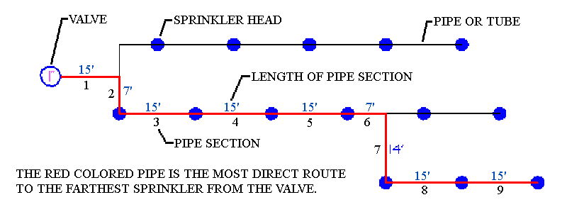
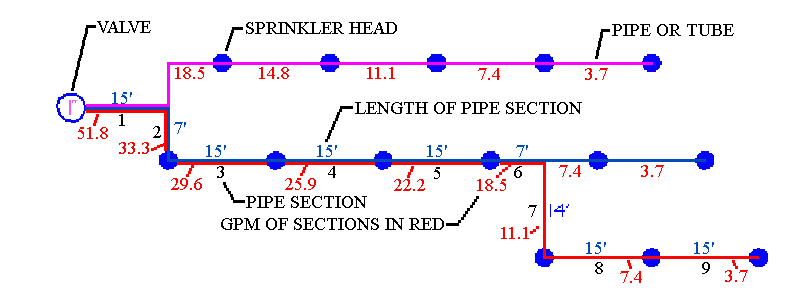
This valve circuit involves numerous paths the water may have. This makes the calculation a bit more complex, every bit a separate calculation is needed for each possible route that the water might take through the laterals on information technology's mode to the final sprinkler at the end of a pipe. If y'all look at the example higher up you will detect at that place are 3 sprinklers that are at the end of pipes, each sprinkler at the terminate of a pipage represents a different road the water can take. So this circuit has 3 and will therefore require 3 separate pressure loss calculations. The next drawing shows the possible water routes in magenta, blue, and carmine colors.

It may assistance to recall of each path as the shortest route that a single drop of water could take to become from the valve to the last sprinkler on a pipage co-operative. For some people it helps to think of information technology as a road map and your looking for the shortest road to each of the dead ends at the end of the roads.
Starting time your calculations with the water road that is the longest. In this instance that would be the road highlighted in ruddy. In that location are 9 pipe sections in this road, I have labeled them 1-9 for clarity. Just as earlier, enter the information from this route into the calculator, and make all the pipage 3/4″ size. Here'southward what the spreadsheet looks like:

As you tin see there are a number of pipe sections highlighted carmine due to dangerous velocity. Alter those pipe sections to larger pipe sizes until all the velocities are within safe levels.
Hither's the resulting spreadsheet calculator with the smallest possible pipe sizes. However, notice the Total of All Sections is 4.4 PSI, which is more than than our iv PSI maximum:

So we demand to make some of the pipe sections larger in order to reduce the pressure loss (or friction loss.) Start by increasing the size of one of the the smaller pipe sections. Changing a 3/four″ pipage to a 1″ size is a lot less expensive than changing a 1″ pipe to 1 1/4″. So for the example lets change section 7 from 3/4″ to 1″. Doing that drops the Full of all Sections value to 3.77 in our instance, below the 4 PSI maximum we gear up earlier. And so now everything is proficient, these sizes will piece of work for the "cherry" highlighted water route.

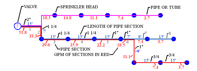
Now nosotros add together the pipe sizes from the spreadsheet to our circuit drawing (note that the pipage sizes for the ruby-red highlighted sections have been added on the next drawing below.)
Now we relabel our sections to follow the bluish highlighted route.

Using the blue highlighted water route, repeat the same process used for the ruby i. Enter the GPM and pipe lengths for each section in the spreadsheet. This time nosotros already know the sizes for sections ane-6, they were entered into the spreadsheet when we did the cherry department. And so we only enter those for the new bluish sections seven and viii, once more using three/four″ size pipe. And it looks similar this on the spreadsheet estimator:

Using 3/4″ pipe size for our ii new sections works good. The velocity is rubber and the Total of All Sections is 3.29 PSI, and so the pressure level loss for this route is also within the 4 PSI maximum we set. Write the size of the ii new sections on the cartoon and the blue water route is done.
At present all that remains is to practise are the calculations for the magenta highlighted water route. That is done the same fashion, entering the data into the spreadsheet computer for each pipe section. Commencement with 3/4″ so change to larger sizes until the velocity is safe. Then bank check that the full of all Sections is less than 4 PSI as earlier. Here's the information entered into the spreadsheet figurer:

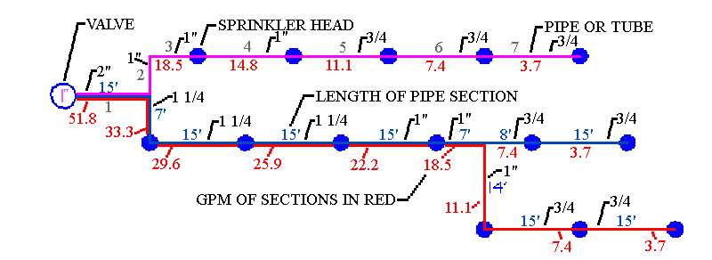
Now all that remains is to insert our lateral pipe sizes from the spreadsheet calculators into the drawing of the valve excursion.

All done! So the pressure loss for the entire circuit is the aforementioned as that for the highest water route. In this case the red route was highest at 3.77 PSI. And then the pressure loss for the lateral circuit shown here is three.77 PSI.
Often I become asked at this betoken why the "Total of all Sections" pressure level losses for all 3 routes wasn't added together? The pressure loss for the red route was 3.77 PSI, for the blue section it was iii.29 PSI, and for the magenta route it was iii.02 PSI. So the defoliation is that it seems like there should be a total loss of x.08 PSI! Nope, the pressure loss for the entire lateral is 3.77 PSI, the loss of the highest route. To understand this think of a single driblet of water once again. It tin can only travel on ane route from the valve to the farthest sprinkler. It is not going to go backwards and endeavour another route! So the pressure level loss for the entire valve circuit is equal to the pressure loss from the valve to the farthest sprinkler.
Previous Page of Tutorial Sprinkler Design Tutorial Index Side by side Page of Tutorial
How Many Sprinkler Heads Per Pipe Size,
Source: https://www.irrigationtutorials.com/calculating-sprinkler-system-pipe-size-using-a-spreadsheet/
Posted by: campbellsplad1984.blogspot.com


0 Response to "How Many Sprinkler Heads Per Pipe Size"
Post a Comment